This is an old revision of the document!
Table of Contents
1420 MHz
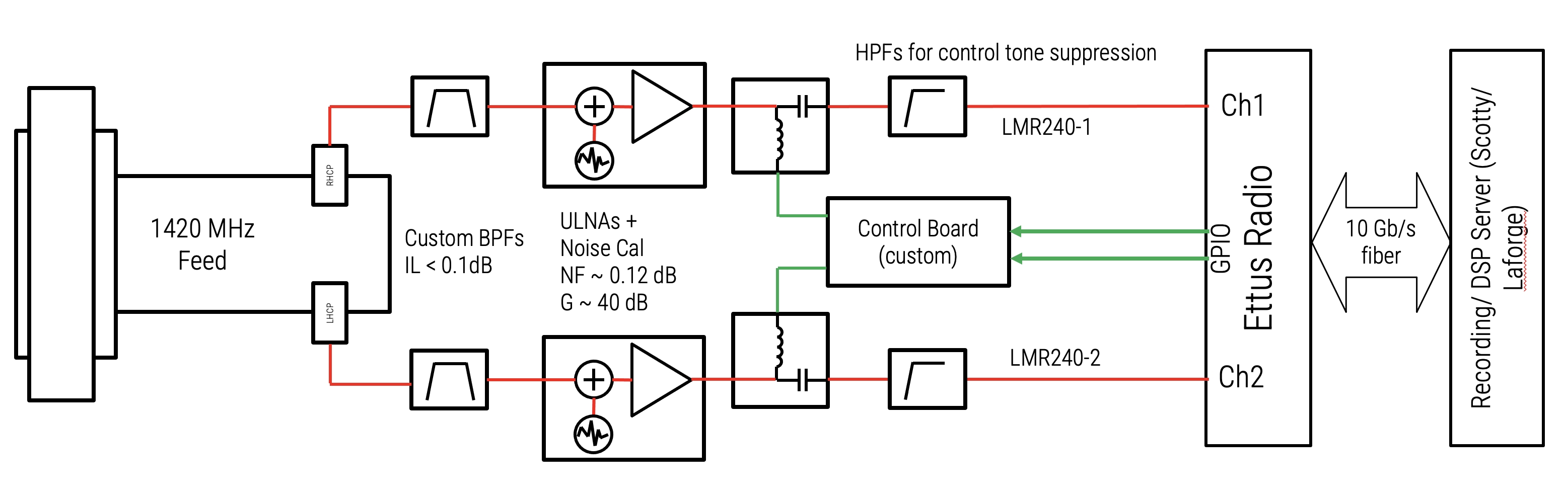
The 1420 MHz frontend is a receive-only system designed by Daniel Sheen (KC1EPN) for radio astronomy. It is tuned to 1420 MHz for the hydrogen emission line and incorporates custom bandpass filters to reject high power OOB signals which otherwise overload the LNAs. The LNAs used are the first generation Indium Phosphide devices designed for the deep synoptic array, and incorporate noise calibration diodes which are used for amplitude and phase calibration of the full RX chain.
Tsys for this frontend is around 45 K within the 1420 MHz protected band (1400 - 1427 MHz), and it has a gain of about 36.3 dBi. Performance degrades rapidly outside of the band.
LNAs
The LNAs are indium phosphide devices incorporating an internal noise calibrator diode. These were originally designed for the Deep Synoptic Array and produced by Cosmic Microwave Technology. More details can be found in the original papers on them on IEEE Xplore:
Low Noise Amplifier With 7-K Noise at 1.4 GHz and 25 ◦C
Temperature Compensated Internal LNA Noise Calibration Source
Additionally, we performed our own measurements at Haystack during early testing which are documented here:
2023.003_cmt_ulna_measurements_at_haystack.pdf
These devices receive calibrator control signals and power over their RF output connector. A dedicated control board located at the feed generates the required voltages and control tones and is in turn commanded by the SDR GPIO.
RF System and Performance
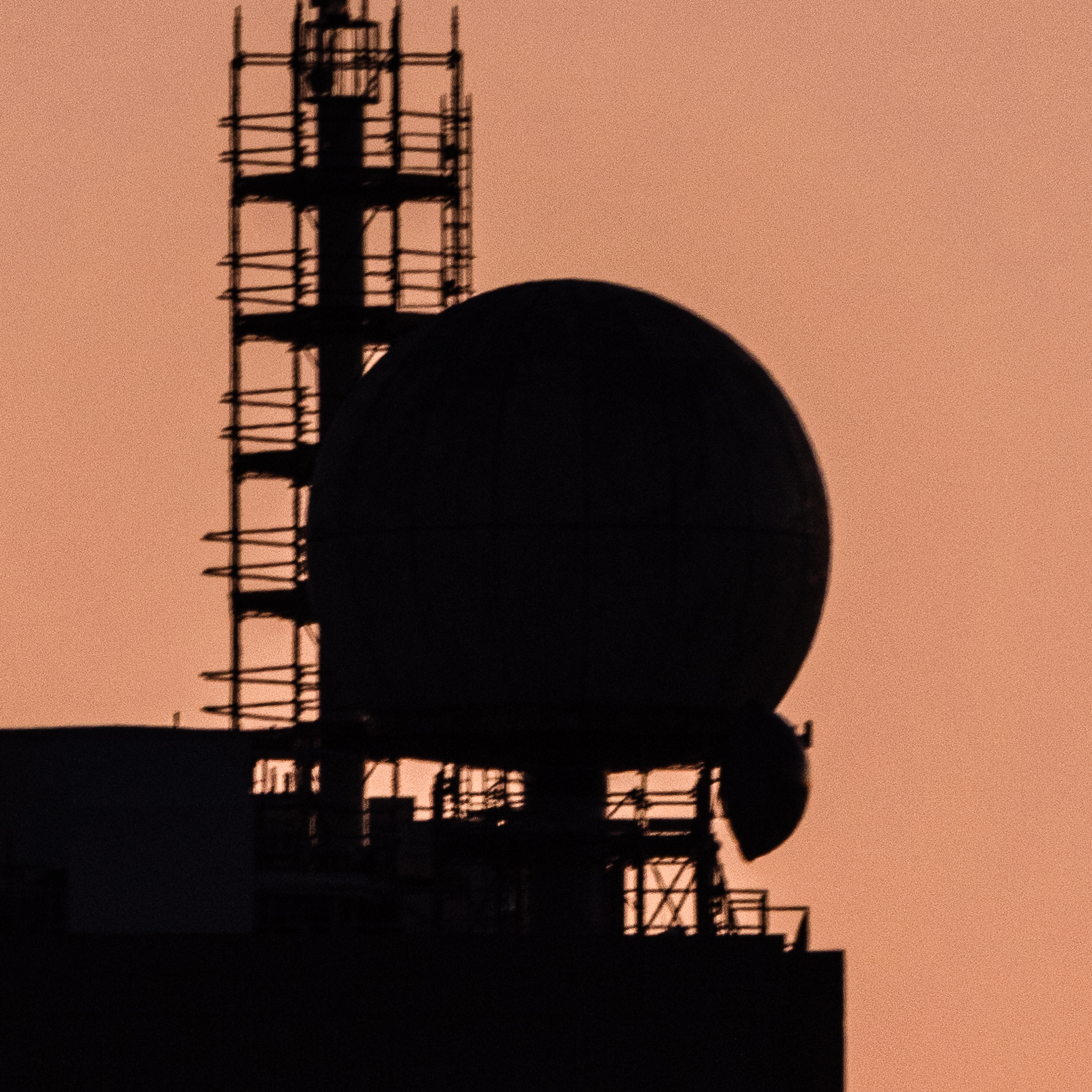
The 1420 MHz feed is a dual-polarized septum feed. One port receives left-hand-circular polarization and the other receives right-hand-circular polarization. More details on the original design and measurement of the feed may be found here:
2023.001_a_1420mhz_septum_feed_for_wr66.pdf
A subsequent, more detailed analysis of the system performance (prior to upgrades which substantially improved the system temperature) may be found here:
Note that the performance of the system in its current configuration was dramatically improved by the installation of lower loss filters ahead of the LNAs. The current G/T and system temperature curves are shown below.

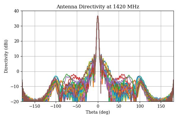
An accurate model for the antenna gain pattern can be found on github in ticra format, along with scripts to read and manipulate it as needed for modeling observations:
https://github.com/dsheen2019/BigDishTools/tree/main/antenna_data
The actual beamwidth is approximately 2.9 degrees with 36.3 dBi gain and between 25 and 26 dB suppression of the first sidelobe. The pattern is depicted below, and is discussed in further detail in
6_meter_dish_2024_001_antenna_pattern_modelling_and_measurement_overview.pdf
The filters used for the frontend are described in detail in the two memos below. They add about 6 K of additional noise ahead of the LNAs, which is about a 20 K improvement over devices from minicircuits which were originally used for the first year of operation. Note that these limit operation to strictly within the 1420 MHz band and fall off rapidly outside of it.
6_meter_dish_memo_2025_002_ultra_low_insertion_loss_1420mhz_filter.pdf
TODO: Link simulations, analysis, electromagnetic simulations, calculated gain pattern, etc.
Control Interface
Calibrator control is via a dedicated control board located at the feed. This board accepts 12 V power and two opto-isolated GPIO pairs, and provides a 5 V supply for the LNA summed with the calibrator control tones. These are then combined with the RF lines from the LNAs by minicircuits bias tees.
https://github.mit.edu/w1xm/ULNA_Bias_and_CTL_v2.git[Control Board Kicad Files
The calibrator signals for the two channels are enabled by a 3.3V active high signal on outputs 0 and 1 of the Ettus X300 radio GPIO. Setting this requires running the following commands to configure the radio correctly:
usrp0.set_gpio_attr(FP0A, CTRL, 0x000, 0xFFF ^ 0b11) #set first two bits to manual control
usrp0.set_gpio_attr(FP0A, DDR, 0xFFF, 0b11) #set first two bits as output
After which the desired output stat may be set by
usrp0.set_gpio_attr(FP0A, OUT, <desired state>, 0b11)
This can be implemented as a python snippet within gnuradio companion flowgraphs (note the correct alias for the radio must be used). Alternately, if using thor.py for recording, message passing can be used using the code here:
https://github.com/dsheen2019/BigDishTools/tree/main/radio_client
Other Documents
See Also:
MRT Phase and Amplitude Calibration implementation details. Relevant tot the calibration of standalone observations, and to the implementation internal to srt.py (srt-py:dual-polarization
polarimeter_phase_calibration.pdf
6_meter_dish_memo_2025_001_computing_stokes_parameters_from_observations.pdf