This is an old revision of the document!
Table of Contents
Overview
The RF systems of the radome allow it to fulfill multiple operating modes:
* Radio astronomy telescope (receive-only on 1420 MHz)
* Satellite uplink (half-duplex on 440 MHz)
* Amateur radio (half-duplex on 440 MHz, 1296 MHz, and others)
Feeds
Each operating mode of the radome uses a different feed, which is an antenna that mounts onto the dish. The feeds are designed to have a common mounting system and compatible electrical interface so that they can be quickly swapped.
TODO: Link mechanical specification for standard feed mounting system
TODO: Document electrical connections for standard feed control/power interface
RF Slipring
An RF slipring is used to pass low power rx/tx signals through the azimuth rotation. It has channels spanning DC to 40GHz. other than the center channel, these are not broadband and can only be used over a limited range of frequencies. The characteristics of these channels mean that they do not lend themselves well to simple filter band descriptions, and a review of the plotted transmission data is generally necessary to make an appropriate routing choice for a new system. This data and associated plots may be downloaded here:
Note that the center channel (DC to 40GHz) is reserved pending the installation of appropriate switches and filter tees. However, it will likely become the default path for all half-duplex systems in order to minimize switching/routing requirements. All channels except the center channel use SMA connectors. The center channel uses SSMA (“small” SMA). These are not mechanically compatible with any other connector type and require adapters to use.
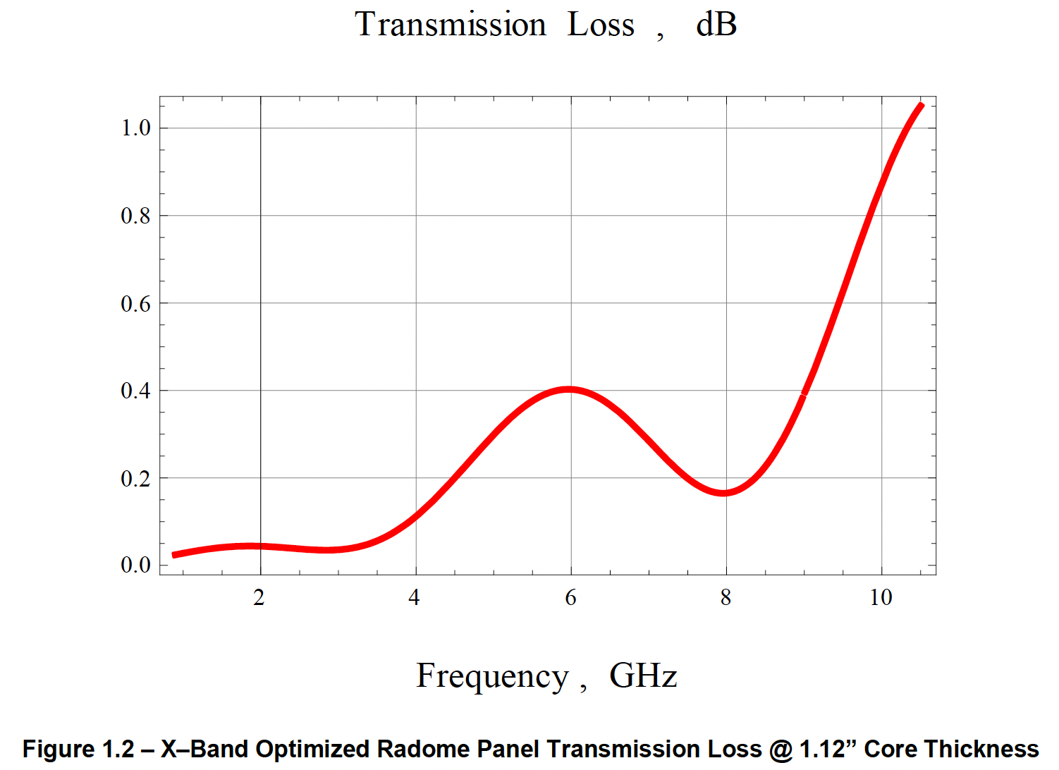
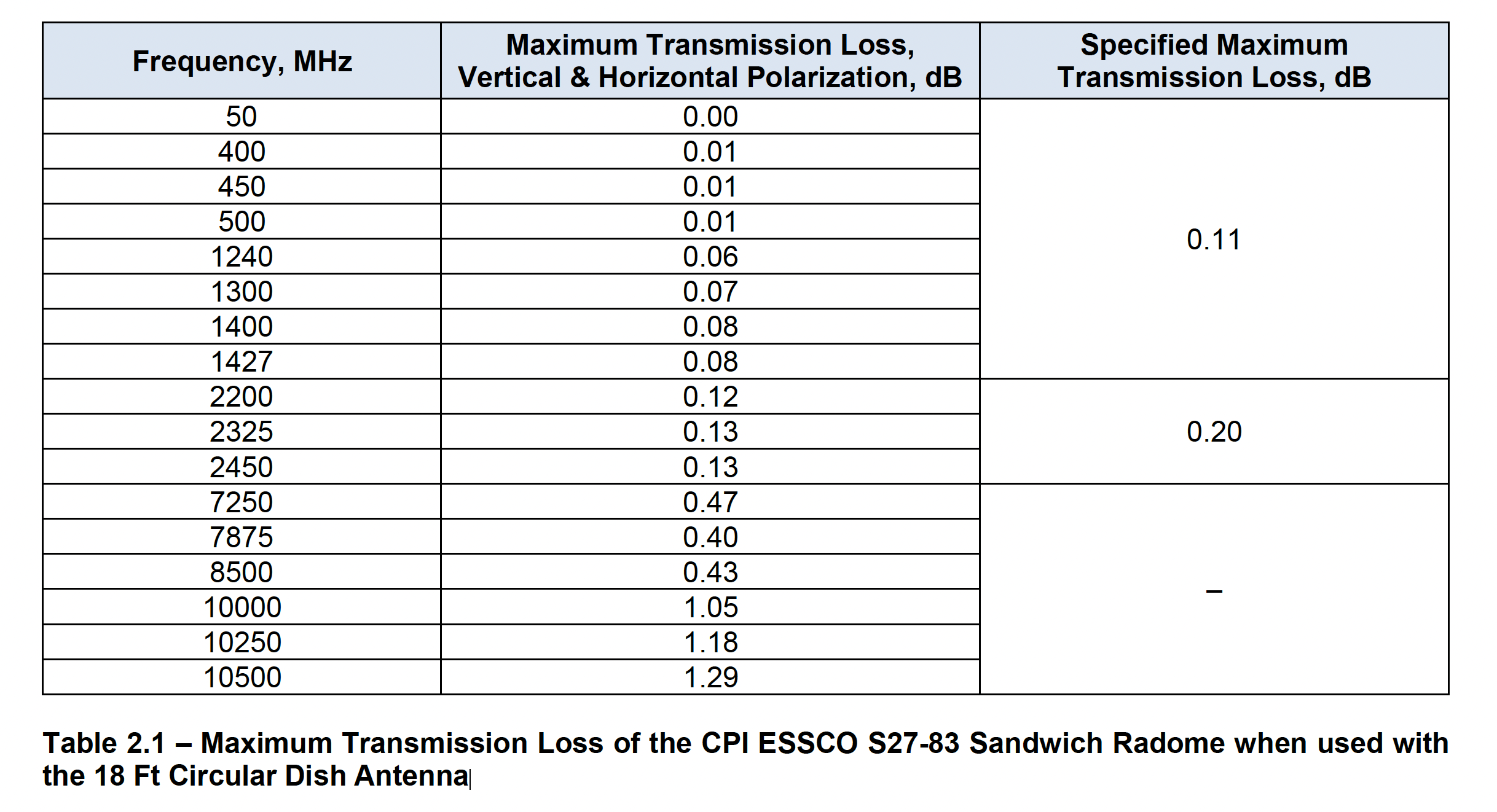
Radome
The radome itself is not perfectly transparent at all frequencies. Its estimated transmission loss is given by the plot below, but the exact performance depends on the exact parameters of the telescope beam and the concentration of energy at different angles of incidence on the radome panels.