start
Differences
This shows you the differences between two versions of the page.
| Both sides previous revisionPrevious revisionNext revision | Previous revision | ||
| start [2025/02/09 18:37] – w1xm | start [2026/05/18 00:33] (current) – [Structure of Radome Systems] dsheen | ||
|---|---|---|---|
| Line 13: | Line 13: | ||
| ===== Structure of Radome Systems ===== | ===== Structure of Radome Systems ===== | ||
| + | |||
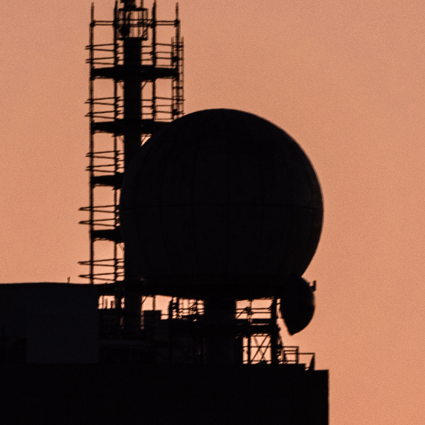
| + | {{ : | ||
| The radome is located on a steel column on the roof of building 54. At the base of the pedestal, there is a climate-controlled rack containing networking equipment, a control computer, and radios. | The radome is located on a steel column on the roof of building 54. At the base of the pedestal, there is a climate-controlled rack containing networking equipment, a control computer, and radios. | ||
| - | The radar dish is mounted on an SCR-584 radar rotor that has been modified with a modernized motion control system. The radar rotor sits on a steel pedestal within the radome. There is an RF rotary coupler and rotating table hanging under the pedestal to allow for mounting equipment like power amplifiers. | + | The radar dish is mounted on an SCR-584 radar rotor that has been modified with a modernized motion control system. The radar rotor sits on a steel pedestal within the radome. There is an RF rotary coupler and rotating table/ |
| The motion control system is controlled over CANbus, which runs to the control computer in the climate-controlled rack. | The motion control system is controlled over CANbus, which runs to the control computer in the climate-controlled rack. | ||
| - | LMR-400 RF cables connect the non-rotating lower portion of the RF rotary coupler to the radio(s) in the climate-controlled rack. | + | LMR-400 RF cables connect the non-rotating lower portion of the RF rotary coupler to the radio(s) in the climate-controlled rack. Additionally, |
| - | Fiber optic cables connect the software-defined radio in the rack to more powerful servers in the 19th floor server room. | + | Fiber optic cables connect the software-defined radio in the rack to a switch in 54-2101 and to more powerful servers in the 19th floor server room. |
start.1739126250.txt.gz · Last modified: 2025/02/09 18:37 by w1xm